Showing posts with label A-Level 9702. Show all posts
Monday, July 22, 2019
9702/May June/4/2003/Q1
(a) Define gravitational potential.
(b) Explain why values of gravitational potential near to an isolated mass are all negative.
(c) Earth may be assumed to be an isolated sphere of radius 6.4 × 10³ km with its mass of 6.0 × 1024 kg concentrated at its centre. An object is projected vertically from the surface of the Earth so that it reaches an altitude of 1.3 × 10⁴ km.
Calculate, for this object,
(i) change in gravitational potential,
(ii) speed of projection from the Earth’s surface, assuming air resistance is negligible.
(d) Suggest why the equation
v2 = u2 + 2as
is not appropriate for calculation in (c)(ii).
Solution:
(a) Gravitational potential (at a point) is defined as the work done in bringing/moving unit mass from infinity to the point.
(b) The potential at infinity is defined as being zero. The forces are always attractive, so work got out in moving to point (work is done on the mass when moving it to infinity).
(c)(i)
Gravitational potential, φ = - GM / R = - GM × (1/R)
{The distances should be converted in metre. Initial position is at the surface of the Earth, which is a distance of 6.4×10⁶m from the centre of the Earth. The final distance is 1.3×10⁷m (altitude = distance above surface) + 6.4×10⁶m (distance of surface of the centre) = 1.94×10⁷m}
Change in potential = (6.67×10⁻¹¹) (6.0×1024) × ({6.4×10⁶}-1 – {1.94×10⁷}-1)
Change in potential = 4.19 × 10⁷ J kg-1 (ignore sign)
(ii)
The kinetic energy is converted to gravitational potential energy as the height of the object from the surface of the Earth increases.
½ mv2 = mΔφ
v2 = 2 × 4.19×107 = 8.38 × 10⁷
Speed v = 9150 m s-1
(d) The acceleration is not constant.
Reference: Past Exam Paper – June 2003 Paper 4 Q1
Tuesday, July 9, 2019
9702/Oct Nov/11/2010/Q13
A rigid L-shaped lever arm is pivoted at point P.
Three forces act on the lever arm, as shown in the diagram.
What is the magnitude of the resultant moment of these forces about point P?
A 15 N m
B 20 N m
C 35 N m
D 75 N m
Answer: A.
We need to consider which forces will cause a clockwise moment and which cause an anticlockwise moment, that is consider how the lever would rotate about P due to each force.
Clockwise moment is caused by the 5N upward and 10N horizontal forces.
Anticlockwise moment is caused by the 15N downward force.
As for the distances, we need to consider the perpendicular distances from the line of action of the forces from point P.
Perpendicular distance of 5N force: (3m + 1m) – 2m = 2m
Perpendicular distance of 10N force: 2m
Perpendicular distance of 15N force: 3m
Magnitude of resultant moment = Anticlockwise moment – Clockwise moment
Magnitude of resultant moment = (15 × 3) – [(10 × 2) + (5 × 2)] = 15 N m
Reference: PYQ - Oct/Nov 2010 Paper 11 Q13
Friday, April 5, 2019
Electric Fields tough question 1 (From Note)
In a
simplified model, a uranium nucleus is a sphere of radius 8.0 × 10⁻¹⁵ m.
The nucleus contains 92 protons (and rather more neutrons). The charge on a
proton is 1.6 × 10⁻¹⁹ C. It can be assumed that the charge of these protons acts as if it were all concentrated at the centre of the nucleus.
The nucleus releases an α particle containing two protons (and two neutrons) at
the surface of the nucleus. Calculate
a) the
electric field strength at the surface of the nucleus before emission of the
α-particle,
b) the
electric force on the α-particle at the surface of the nucleus,
c) the
electric potential at the surface of the nucleus before emission of the
α-particle,
d) the
electric potential energy of the α-particle when it is at the surface of the
nucleus.
Solution:
Wednesday, March 20, 2019
9702/May Jun/42/2010/Q10
(a) State the name of an electrical sensing device that will respond to changes in
(i) length,
(ii) pressure.
(b) A relay is sometimes used as the output of a sensing circuit.
The output of a particular sensing circuit is either + 2 V or – 2 V.
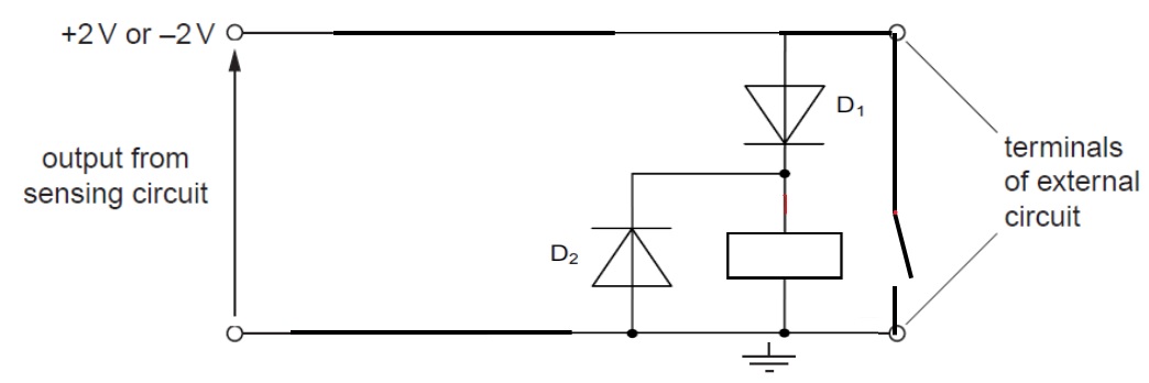
On Fig. 10.1, draw symbols for a relay and any other necessary component so that the
external circuit is switched on only when the output from the sensing circuit is + 2 V.
Solution:
Reference: PYQ - May/June 2010 Paper 42 Q10
https://electronics.stackexchange.com/questions/56322/do-i-need-a-flyback-diode-with-an-automotive-relay/56323#56323
(i) length,
(ii) pressure.
(b) A relay is sometimes used as the output of a sensing circuit.
The output of a particular sensing circuit is either + 2 V or – 2 V.
On Fig. 10.1, draw symbols for a relay and any other necessary component so that the
external circuit is switched on only when the output from the sensing circuit is + 2 V.
Solution:
(a)
(i) Strain gauge
(ii) Piezo-electric / quartz crystal / transducer
(b) For the circuit, a coil of relay is connected between the sensing circuit output and earth and the switch is across the terminals of the external circuit.
A diode is connected in series with the coil with a correct polarity for the diode (downwards). A second diode with correct polarity is connected (upwards and parallel to coil of relay).
{Note that the following explanations have been taken directly from the application booklet.
The diode D1 conducts only when the output is positive with respect to earth and thus the relay coil is energized only when the output is positive. When the current in the relay coil is switched off, a back e.m.f. is generated in the coil that could damage the sensing circuit. A diode D2 is connected across the coil to protect the sensing circuit from this back e.m.f.}
Reference: PYQ - May/June 2010 Paper 42 Q10
Reference links:
https://electronics.stackexchange.com/questions/100134/why-is-there-a-diode-connected-in-parallel-to-a-relay-coilhttps://electronics.stackexchange.com/questions/56322/do-i-need-a-flyback-diode-with-an-automotive-relay/56323#56323
Thursday, March 14, 2019
Capacitor Question 3
(a) A 470 μF capacitor is connected to a 20 V supply. Calculate the charge stored on one plate of the capacitor.
(b) The capacitor in a is now disconnected from the supply and connected to an uncharged 470 μF capacitor.
(i) Explain why the capacitors are in parallel, rather than series, and why the total charge stored by the combination must be the same as the answer to (a).
(ii) Calculate the capacitance of the combination.
(iii) Calculate the potential difference across each capacitor.
(iv) Calculate the charge stored on one plate of each capacitor.
1Q = 20V
(b) The capacitor in a is now disconnected from the supply and connected to an uncharged 470 μF capacitor.
(i) Explain why the capacitors are in parallel, rather than series, and why the total charge stored by the combination must be the same as the answer to (a).
(ii) Calculate the capacitance of the combination.
(iii) Calculate the potential difference across each capacitor.
(iv) Calculate the charge stored on one plate of each capacitor.
Solution:
a)
Q = CV
= (470 x 10^-6) x (20)
= 9.4 mC
bi)
When capacitors are connected in series, the total capacitance is less than any one of the series capacitors’ individual capacitances. If two or more capacitors are connected in series, the overall effect is that of a single (equivalent) capacitor having the sum total of the plate spacings of the individual capacitors. As we’ve just seen, an increase in plate spacing, with all other factors unchanged, results in decreased capacitance.
When capacitors are connected in parallel, the total capacitance is the sum of the individual capacitors’ capacitances. If two or more capacitors are connected in parallel, the overall effect is that of a single equivalent capacitor having the sum total of the plate areas of the individual capacitors. As we’ve just seen, an increase in plate area, with all other factors unchanged, results in increased capacitance.
The total charge stored by the combination must be the same as the answer to (a) is because the total charge of a capacitor is equal to the total charge of both capacitors.
bii)
C = C1 + C2
= 470 uF + 470 uF
= 940 uF
biii)
Q ∝ V1Q = 20V
0.5Q = 10V
biv)
Q1 = (C1) (V)
= (470 uF)(10)
= 4.7 mC
Q2 = (C1) (V)
= (470 uF)(10)
= 4.7 mC
Reference:
Monday, March 11, 2019
Electric Fields Tough Question 1
Two +30 μC charges are placed on a straight line 0.40 m apart. A +0.5 μC charge is to be moved a distance of 0.10 m along the line from a point midway between the charges. How much work must be done?
Solution:
Solution:
Wednesday, February 27, 2019
Examination Style Questions 7 from Oscillations note
The apparatus of Fig. 13.16 is used to demonstrate forced vibrations and resonance. A 50 g mass is suspended from the spring, which has a spring constant of 7.9 N
m−1.
a) Calculate the resonant frequency f0 of the system.
b) A student suggests that resonance should also be observed at a frequency of 2 f0. Discuss this suggestion.
Solution:
a)
b) If the driving frequency is increased further, the amplitude of oscillation of the mass decreases.
Reference: Examination Style Questions 7 from note
Examination Style Questions 5 from Oscillations note
One particle oscillating in simple harmonic motion has ten times the total energy of another particle, but the frequencies and masses are the same. Calculate the ratio of the amplitudes of the two motions.
Solution:
Reference: Examination Style Questions 5 from Oscillations note
Examination Style Questions 2 from Oscillations note
A particle is oscillating in simple harmonic motion with frequency 50 Hz and amplitude 15 mm. Calculate the speed when the displacement from the equilibrium position is 12mm.
Solution:
Reference: Examination Style Questions 2 from note
Examination Style Questions 1 from Oscillations note
A particle is oscillating in simple harmonic motion with period 4.5ms and amplitude 3.0cm. At time t = 0, the particle is at the equilibrium position. Calculate, for this particle:
a)the frequency, b)the angular frequency,
c)the maximum speed,
d)the magnitude of the maximum acceleration,
e)the speed at time t = 1.0 ms.
Solution:
Reference: Examination Style Questions 1 from Oscillations note
Saturday, February 23, 2019
Tough Question 1 (Chapter: Production and use of ultrasound in diagnosis)
A
parallel beam of ultrasound passes through a thickness of 4.0 cm of muscle. It
is then incident normally on a bone having a specific acoustic impedance of 6.4
× 106 kg m−2 s−1. The bone is 1.5 cm thick. Using data
from Table
14.2,
calculate the fraction of the incident intensity that is transmitted through
the muscle and bone.
Table
14.2 Some values of linear absorption
(attenuation) coefficient for ultrasound
Thursday, November 15, 2018
9702/May Jun/12/2015/Q6
A single sheet of aluminium foil is folded twice to produce a stack of four sheets. The total thickness of the stack of sheets is measured to be (0.80 ± 0.02) mm. This measurement is made using a digital caliper with a zero error of (−0.20 ± 0.02) mm.
What is the percentage uncertainty in the calculated thickness of a single sheet?
A 1.0% B 2.0% C 4.0% D 6.7%
Solution:
Answer: C
This challenging question involves both random and systematic error.
The zero error (−0.20) can be removed but its uncertainty (± 0.02) must be added to the measurement uncertainty.
True value of total thickness = 0.80 + 0.20 = 1.0 mm
Total uncertainty in measurement = ± (0.02 + 0.02) = ± 0.04
So the four sheets have a true thickness of (1.00 ± 0.04) mm.
A single sheet would have a thickness of (0.25 ± 0.01) mm.
Percentage error = (0.01 / 0.25) × 100% = 4%
Reference: PYQ - Oct/Nov 2015 Paper 12 Q6
9702/May Jun/11/2018/Q34
In the circuit shown, the batteries have negligible internal resistance.
What are the values of the currents I1, I2 and I3?
Solution:
Answer: C
Reference: PYQ - May/Jun 2018 Paper 11 Q34
Wednesday, November 14, 2018
9702/Oct Nov/12/2016/Q24
A transverse progressive wave of wavelength λ is set up on a stretched string. The graph shows
the variation of displacement y with distance x at a particular instant of time. The displacement
where distance x = λ/8 is y1.
What are the next two values of x where the displacement y is again equal to y1?
the variation of displacement y with distance x at a particular instant of time. The displacement
where distance x = λ/8 is y1.
Solution:
Answer: B
From the figure above, it is very obvious the option C and D are incorrect.
The answer is "B" is because the second value of x must more than λ.
Reference: PYQ - Oct/Nov 2016 Paper 12 Q24
Tuesday, November 13, 2018
9702/Oct Nov/11/2016/Q11
A car has mass m. A person needs to push the car with force F in order to give the car
acceleration a. The person needs to push the car with force 2F in order to give the car
acceleration 3a.
Which expression gives the constant resistive force opposing the motion of the car?
A ma
B 2ma
C 3ma
D 4ma
acceleration a. The person needs to push the car with force 2F in order to give the car
acceleration 3a.
Which expression gives the constant resistive force opposing the motion of the car?
A ma
B 2ma
C 3ma
D 4ma
Solution:
Answer: A
Resultant force = applied force – resistive force
Ma = F- R
R = F- ma —-i
3ma = 2F – R
R = 2F – 3ma —–ii
Substitute for R in eq i
2F – 3ma = F – ma
F = 2ma
Therefore, R = 2ma – ma = ma
Resistive force = ma (A is the correct option)
Reference: PYQ - Oct/Nov 2016 Paper 11 Q11
Monday, November 12, 2018
9702/Oct Nov/13/2013/Q38
A 20 V d.c. supply is connected to a circuit consisting of five resistors L, M, N, P and Q.
There is a potential drop of 7 V across L and a further 4 V potential drop across N.
What are the potential drops across M, P and Q?
Solution:
Answer: C
This question can be easily tackled by considering the different loops present in the circuit and apply Kirchhoff’s laws to them.
Consider the loop: ‘+’ terminal supply – resistor L – resistor M – ‘-’ terminal supply
From Kirchhoff’s law, the sum of p.d. across any loop should be equal to the e.m.f. Analysis of the loop shows that a 7 V drop across resistor L must mean a 13V drop across M (to obtain a total 20V across L and M).
Notice that the direction of potential drop is also of significance.
Consider resistor L for example. The direction of potential drop is from left to right. Current flows from the ‘+’ terminal of the supply, so the junction on the left of resistor L should be at a higher potential (which is equal to 20V since there is no component between it and the ‘+’ terminal of the supply).
So, the direction of potential rise is from a greater value of potential to a small value of potential. Additionally, current flows from a greater potential to a smaller potential (as in the case of the ‘+’ terminal of the supply).
The junction between L and M is at a potential of 13V (since the right junction to which M is connected is at 0V as it is connected to the ‘-’ terminal of the supply).
There is a potential drop of 4V downwards across N, so current flows downwards. This means that the potential at the upper junction (between L and M) is greater than the lower junction (between P and Q) and the difference in potential is 4V.
Thus, lower junction (between P and Q) is at a potential of (13V – 4V =) 9V
So, the potential drop across resistor Q is 9V (since the right junction to which Q is connected is at 0V as it is connected to the ‘-’ terminal of the supply).
Finally, consider resistor P. Its terminal is at a potential of 20V and its right terminal is at a potential of 9V. Potential drop = 20 – 9 = 11V.
Important notice:
When considering a loop, it should start from one terminal of the supply and end at the other terminal. Only then will Kirchhoff’s law apply. For example, ‘+’ terminal supply – L – N – P – ‘+’ terminal supply is not a correct loop. You may notice that the sum of p.d. is not equal to the e.m.f. Additionally the flow of current is wrong.
Reference: PYQ - Oct/Nov 2013 Paper 13 Q38
Subscribe to:
Posts (Atom)