Wednesday, March 20, 2019

9702/May Jun/42/2010/Q10

(a) State the name of an electrical sensing device that will respond to changes in
(i) length,
(ii) pressure.

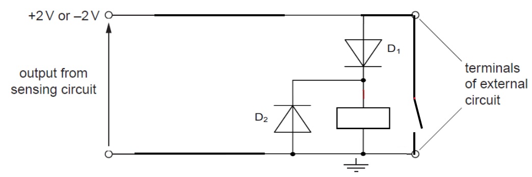
(b) A relay is sometimes used as the output of a sensing circuit.
The output of a particular sensing circuit is either + 2 V or – 2 V.
On Fig. 10.1, draw symbols for a relay and any other necessary component so that the
external circuit is switched on only when the output from the sensing circuit is + 2 V.


Solution:
(a)
(i) Strain gauge
(ii) Piezo-electric / quartz crystal / transducer

(b) For the circuit, a coil of relay is connected between the sensing circuit output and earth and the switch is across the terminals of the external circuit.
A diode is connected in series with the coil with a correct polarity for the diode (downwards). A second diode with correct polarity is connected (upwards and parallel to coil of relay).
{Note that the following explanations have been taken directly from the application booklet.
The diode D1 conducts only when the output is positive with respect to earth and thus the relay coil is energized only when the output is positive. When the current in the relay coil is switched off, a back e.m.f. is generated in the coil that could damage the sensing circuit. A diode D2 is connected across the coil to protect the sensing circuit from this back e.m.f.}


Thursday, March 14, 2019

Capacitor Question 3

(a) A 470 μF capacitor is connected to a 20 V supply. Calculate the charge stored on one plate of the capacitor.
(b) The capacitor in a is now disconnected from the supply and connected to an uncharged 470 μF capacitor.
(i) Explain why the capacitors are in parallel, rather than series, and why the total charge stored by the combination must be the same as the answer to (a).
(ii) Calculate the capacitance of the combination.
(iii) Calculate the potential difference across each capacitor.
(iv) Calculate the charge stored on one plate of each capacitor.


Solution:
a)
Q = CV
= (470 x 10^-6) x (20)
= 9.4 mC

bi)

When capacitors are connected in series, the total capacitance is less than any one of the series capacitors’ individual capacitances. If two or more capacitors are connected in series, the overall effect is that of a single (equivalent) capacitor having the sum total of the plate spacings of the individual capacitors. As we’ve just seen, an increase in plate spacing, with all other factors unchanged, results in decreased capacitance.

When capacitors are connected in parallel, the total capacitance is the sum of the individual capacitors’ capacitances. If two or more capacitors are connected in parallel, the overall effect is that of a single equivalent capacitor having the sum total of the plate areas of the individual capacitors. As we’ve just seen, an increase in plate area, with all other factors unchanged, results in increased capacitance.
The total charge stored by the combination must be the same as the answer to (a) is because the total charge of a capacitor is equal to the total charge of both capacitors.

bii) 
C = C1 + C2
= 470 uF + 470 uF
= 940 uF

biii)
Q ∝ V
1Q = 20V

0.5Q = 10V

biv)
Q1 = (C1) (V) 
= (470 uF)(10)
= 4.7 mC

Q2 = (C1) (V) 
= (470 uF)(10)
= 4.7 mC

Reference:

Monday, March 11, 2019

Electric Fields Tough Question 1

Two +30 μC charges are placed on a straight line 0.40 m apart. A +0.5 μC charge is to be moved a distance of 0.10 m along the line from a point midway between the charges. How much work must be done?

Solution: